

Now that I have my full UniFi network build at my house, I am finishing up documenting everything. One aspect of UniFi that I really enjoy is their InnerSpace tool which allows one to import their floorplans (or build them), add UniFi devices and their locations, and then be able to see things such as Wi-Fi coverage, potential issues or improvements, as well as camera locations and their visible areas.
What is UniFi InnerSpace?
UniFi InnerSpace is an application built for the UniFi OS ecosystem (by Ubiquiti) that provides visual deployment and site-map capabilities for your network and security devices. In short: you upload or draw a floorplan (for a home, office, building, etc.), place devices inside it (APs, cameras, switches, etc.), draw walls/rooms, and then view coverage maps (e.g., Wi-Fi signal, camera fields, etc.).
From the release notes: “A powerful deployment visualization tool that allows you to view your UniFi system’s Wi-Fi and camera coverage over your floorplan.”
Key capabilities include:
Uploading a floorplan image (or drawing directly) and setting scale.
Drawing walls, windows, etc., so that coverage maps (for Wi-Fi, cameras) can take physical obstructions into account.
Drag-and-drop your UniFi devices into the plan — the devices list integrates with your UniFi OS environment (so it pulls your existing APs, cameras, etc.).
Viewing heatmaps or coverage blobs for Wi-Fi (based on antenna patterns) and camera view cones.
As of later versions: support for 3D floorplan visualization (extruding walls, multilevel) in the 1.2.0 release.
In short: It’s a “site visualizer” for UniFi gear — especially helpful when planning deployments (new offices, home network upgrades, multi-floor environments).
What it can do (and how that might help you)
Given your home/office setup (you have UniFi gear at the office, and a sophisticated PC build, and you’re combining network/Windows Server projects) here are ways InnerSpace could add value:
Planning Wi-Fi coverage: For your office (where you’re setting up a UniFi Dream Machine, switches, etc.), you could import the floorplan, draw walls/rooms, place APs, and visualize coverage gaps or overlap. Helps avoid “we placed the AP, but the corner has weak signal” surprises.
Camera placement & field of view: If you have UniFi Protect cameras at the office (or plan to), you can place them on the map and see their view cones / coverage zones.
Physical network layout documentation: You could use InnerSpace to show visually where everything is placed (rack, switches, access points, cable runs) and how coverage ties in.
Edge/ceiling orientation & obstacles: By drawing walls, windows, and obstacles, you get a more realistic view of signal propagation — important when you have unusual spaces (e.g., large meeting rooms, server room, concrete walls).
Multi-floor / 3D support: For an office with, say, upstairs/downstairs, or a mezzanine, the newer 3D feature (in 1.2.0) helps you visualize vertical coverage too.
Benefits
Better planning: Instead of placing devices and “hoping for the best,” you can visualize first.
Documentation / presentation: For clients, colleagues, etc., it gives a visuals-rich layout of the network.
Improved coverage results: By modelling walls/obstacles and device placement, you’re more likely to get good signal, fewer dead-zones.
Leverage existing inventory: It integrates into UniFi OS so your devices appear automatically (less manual work).
Future-proofing for multi-floor / 3D: With the 3D features, you can plan for vertical stacking/spaces.
Issues / Limitations (what to watch out for)
As with any tool, there are caveats — some are already noted by users:
Bugs / immature UI: In early versions, some users reported the app wouldn’t launch properly on certain hardware (e.g., on a UDM Pro).
Wall/obstacle modelling still requires effort & accuracy: Some users say unless you draw walls/windows properly and set their properties, the heatmap may not be realistic.
Orientation / antenna modelling weirdness: Some AP coverage shapes looked odd (some users suspect incorrect antenna data, or lacking orientation controls).
Single-floor bias / early 3D support: The multi-floor/3D features are newer, so perhaps less mature: upload floorplan + extrusion may take more manual effort.
Learning curve & accuracy trade-offs: While helpful visually, it’s not a perfect substitute for full RF site-survey tools. It is based on modelling/approximation.
Performance/UI responsiveness: Some users noted UI feels sluggish on large plans or many devices.
Feature gaps: Some expected features (e.g., rotating wall-mounted APs, detailed antenna orientation) may be less intuitive or missing.
How to set it up: step by step
I’ll walk you through a setup flow (assuming you already have a brand-new office or are upgrading an existing office/home network). You’ll adapt to your environment (your office network with the UniFi Dream Machine etc.).
Prerequisites
A UniFi OS environment: e.g., a UniFi Dream Machine or Dream Machine Pro, or a UniFi OS Console.
The InnerSpace application installed in the UniFi OS (from the Applications section).
A floorplan (image, PDF, or you’ll draw a blank plan).
Knowledge of where your walls/rooms/devices are going to live.
Step 1: Install InnerSpace
1. Login to your UniFi OS console.
2. Navigate to “Applications” (or “Apps”) and locate “InnerSpace.”
3. Install (or update) to the latest version. For example, version 1.1.22 added Protect & Access integration.
4. Launch InnerSpace. On some systems the launch icon may be small or tucked in a corner (users have noted this).
Step 2: Create or import your floorplan
1. In InnerSpace, click to create a new site (or edit existing).
2. Upload an image of your floorplan (e.g., OfficeFloorPlan.png) OR choose to draw your own walls/rooms manually.
3. Set the scale: You’ll need to define a known length (e.g., measure a corridor, 10 feet = 3.048 m) so the tool knows real-world dimensions.
4. If you imported an image, align it properly (rotate/zoom) so north/up-map corresponds to real orientation if needed.
Step 3: Draw walls, rooms, obstacles
1. Select the “Wall” drawing tool (or “Room”/“Obstacle” depending on version).
2. Trace the walls of your floorplan (or draw new ones). Mark interior walls, exterior walls, windows/doors if supported. Some UI elements let you assign “wall type” or “material” (which affects signal attenuation) — check your version.
Example: On Reddit some users complained they didn’t actually draw walls and then the coverage shapes looked unrealistic.
3. If you have multi-floor, you may choose to draw separate floors and assign floor numbers/height. For 3D visualisation (in version 1.2.0+) you may extrude the walls.
4. Save your layout.
Step 4: Add devices (APs, Cameras, Switches)
1. On the device-panel, you should see all your UniFi devices (APs, cameras, switches) that are adopted by your UniFi OS controller. InnerSpace pulls from that device inventory.
2. Drag-and-drop each AP or camera to its location on the floorplan (ceiling mount vs wall mount, etc.).
3. For APs: orient the device icon if orientation is supported (some models allow rotation to simulate directional coverage). Users noted some confusion here:
> “You haven’t actually assigned any walls… Then your APs will show up as ceiling or wall-mounted … you can rotate the orientation a full 360 degrees of the wall-mounted ones if you want.”
4. For cameras: place them where they would physically sit, and the view-cone should appear (depending on version/model support).
5. You can also layer in other devices (switches, etc.) but coverage maps focus mostly on APs/cameras.
Step 5: View coverage / heatmaps / analytics
1. In InnerSpace select the “Coverage” or “Heatmap” view. Choose the type: Wi-Fi signal, camera view, etc.
2. For Wi-Fi, the tool uses antenna models (for supported APs) to simulate radiation patterns. Version 1.1.1 added “updates Wi-Fi coverage to use more precise AP radiation patterns.”
3. Observe coverage. Look for weak-zones, overlapping coverage (which may cause co-channel interference), blind spots behind thick walls, etc.
4. Adjust device placement or wall modelling to optimise: e.g., move an AP a bit, reduce obstruction, change orientation.
5. For 3D layouts: switch to the 3D view (if supported) to visualise multi-floor coverage and vertical bleed-through.
6. Export / document / integrate
InnerSpace may allow you to export the plan or generate screenshots. Use those for your internal documentation.
Save the project so you can revisit when you upgrade gear, add new rooms, etc.
For your office network: you could use InnerSpace maps as part of your network documentation library (alongside your UniFi firewall/switch diagrams).
How to insert walls (detailed)
Because inserting walls is a crucial step (and sometimes where users get stuck), here’s a more detailed breakdown:
1. Choose the wall-drawing tool. In some versions the tool will let you choose “Wall,” “Window,” “Door,” “Room,” etc.
2. Click on the floorplan where you want to start the wall. Move the mouse to draw the line segment, click again to end. For standard rooms you’ll typically trace each wall segment.
3. If you have interior partitions, doors, or windows, you can draw those and set their type (if the UI supports). Windows typically have less attenuation than solid walls.
4. If the plan is complicated (curved walls, columns, shafts) you may approximate with straight segments.
5. After drawing: you may be able to assign properties (wall material, thickness, height) — check your version. The more accurately you model these, the more realistic your coverage simulation will be.
6. Save. Then you can drag devices onto the floorplan and the walls will influence coverage. Walls may block or attenuate signal propagation in the simulation.
7. If you have multiple floors: either draw a separate floorplan for each or, if 3D mode is supported, extrude walls (set height) so that vertical bleed-through is modelled.
For example: On a two-story office, you may place an AP on the ceiling of the first floor; you’ll want to understand how much the second-floor ceiling or floor structure attenuates signal. 3D mode helps here.
8. Adjust as necessary: If you find unexpected weak spots in the heatmap, revisit the wall layout (maybe a wall is mis-drawn) or device placement.
Use case walks (tie-in with your office)
Given your project context (you’re setting up a UniFi Dream Machine, switches), here’s how you might integrate InnerSpace:
Office rollout: Before you unpack APs, run InnerSpace on the floorplan. Map out the meeting room, open-plan office, server room (where your Windows Server might live), common areas, break room. Draw walls (especially server-room walls, which may be thick/metal). Place AP icons where you think you’ll mount them (ceiling tile in office, wall in hallway). Visualize coverage, adjust design accordingly.
Server-room wireless isolation: For your Windows Server area (likely in a rack, wired connection) you may still have Wi-Fi coverage considerations for IT staff or remote access. Using InnerSpace you can show how you keep APs away from server racks (to avoid RF noise) and still cover adjacent offices.
Emergency/troubleshooting: If you ever get Wi-Fi complaints (“weak in meeting room”) you have the InnerSpace map as a reference. You can revisit the plan, see where walls/devices were placed, and adjust accordingly (add an AP, relocate).
Tips & Best Practices
Always measure real-world distances when you set the scale: e.g., measure a corridor in meters/feet and use that as your reference in the plan.
Draw walls/doors/windows even if you think “oh it’s open plan” — better modelling = better estimates.
Consider obstructions other than walls: large server racks, metal filing cabinets, kitchen equipment – these may affect signal especially in office environments.
Don’t rely solely on the simulation: after deployment, run an on-site survey (with e.g., a Wi-Fi analyzer) to validate results.
Keep your InnerSpace plan updated: if you move APs, add devices, change walls (office renovation), update the plan so it remains useful.
Label devices clearly: in the InnerSpace map, name your APs meaningfully (“Office-AP-1”, “MeetingRoom-AP”) so when you document you can refer to them.
Export high-res images of your plan annotated with match-to-physical-layout photos.
For large or multi-floor office: use 3D mode (if available) or separate maps per floor and indicate vertical stacking.
If you’re integrating with your Windows Server environment (for documentation), consider linking the InnerSpace export with your server’s asset documentation (e.g., “ServerRack location corresponds to InnerSpace plan page X”).
Be aware of versioning: the features and UI change between InnerSpace 1.0 → 1.1 → 1.2. Keep your system updated and review the release notes.
Summary
UniFi InnerSpace is a strong tool for anyone working with UniFi gear who wants better visual layout, planning, and documentation of their wireless/camera/switch deployments. For your scenario — building up an office network, integrating UniFi with your server infrastructure — it offers a visually rich way to show “what was planned, where devices are, how coverage behaves”.
Like any tool it has a learning curve and some limitations (accuracy depends on how well you model your physical environment, some UI quirks persist, newer 3D features may be less mature). But I’d say it’s well worth adopting as part of your network toolkit.
My InnerSpace
I have been trying to find the floorplans of our new house build (full interior remodel), but have only been able to locate the basement (which is where most of the network equipment is anyway), so I will begin there.
Here is the floorplan of the basement before uploading into UniFi.
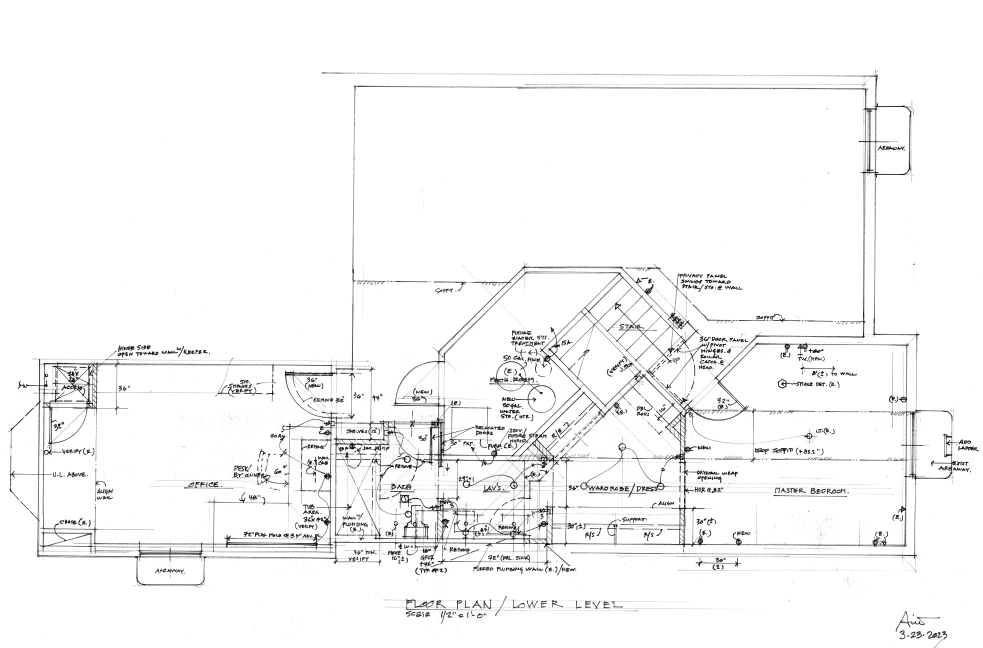
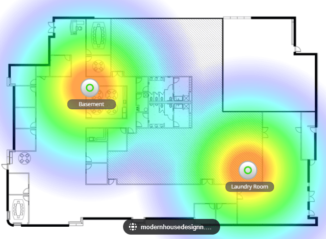
Below, is the current layout of the basement, including the ‘rack’ in the utility room (48-port switch, firewall, E7 access point, UPS, etc.; this is the equipment located in the middle of the image. Note how you can see the Wi-Fi coverage, but for accurate results, setting the scale of the layout, inserting walls (with their composition), and other factors will be helpful (have not done this yet).

Next, we have the UniFi Protect layout for the basement (camera system). I only have 2 UniFi cameras installed, one covering my office’s door, and the other covering the office’s egress window. It is kind of neat to set this up with floorplans as you can see what kind of coverage the cameras have, as well as be able to quickly locate and view the cameras by simply clicking on them in this below layout.

Next up is finding or building the middle and top floorplans!
Categories: Networks


